Technical paper
Impressed current retrofits on offshore platforms: The good, the bad, and the ugly
by Jim Britton (2001)

Abstract
It has long been recognized that an impressed current cathodic protection systems can offer significant economic advantages over galvanic anodes on certain types of offshore platforms which require a cathodic protection retrofit. In many cases however, these advantages have been cancelled out by poor system performance and the economic repercussions that result. This paper will review some historical design philosophies and discuss good and not-so-good points regarding the efficiency and reliability of these systems. Newer designs will be compared, and then some economic comparisons will be presented for specific projects.
Introduction
Many offshore platforms exceed their original design life and thus require a cathodic protection retrofit to facilitate a corrosion-free life extension. The cost-savings of an impressed current design, as well as the seemingly simple design features and installation procedures associated have always attracted cathodic protection designers. It is in large part this apparent simplicity that has led to the failure of many early designs and some more recent attempts. The major causes of system failure can almost always be linked to a designer underestimating the harsh offshore environment. When properly fortified though, impressed current cathodic protection systems are no different than many other electrical and mechanical systems installed offshore; if they are correctly and adequately designed, they will fulfill the required design life.
System economics
Life-cycle cost versus risk of failure is the controlling factor as to whether an impressed current design makes sense or not. When the economics of a cathodic protection retrofit are considered, the dominating number is nearly always installation cost. This is not surprising when the offshore environment is compared to an onshore or inshore location. Table 1 shows a typical economic comparison for a Gulf of Mexico retrofit. Diving costs follow a non-linear curve as depth increases, and the upward cost shift seems to become quite steep at around 200 feet or greater. At these depths divers must switch from conventional air to mixed gas; sometimes a saturation diving spread is required. With this setup, the divers earn more, the support staff and overall number of personnel offshore increases, the size and type of support vessel changes, and all of these factors lead to higher day rate cost.
Table 1
Hybrid retrofit on 210' 0" 8-pile platform, Gulf of Mexico; 755 Ampere of current required. Cost comparison with a conventional aluminum anode retrofit (note: prices based on materials cost in 2001, not valid except to show comparison).
Impressed current cathodic protection (hybrid) option:
| Item | Quantity | Unit | Description |
|---|---|---|---|
| 1 | 3 | pcs | 250 Ampere JCCP Buoyant Sled |
| 2 | 2400 | feet | 4/0 AWG OOSWA Wire (2 per Sled) |
| 3 | 3 | pcs | 250 Amp 24 Volt Oil Immersed Marine Rectifier- Class I Div. 2 Group 0 |
| 4 | 6 | pcs | Zinc Reference Electrode |
| 5 | 3 | pcs | 4"J-Tube Assembly |
| 6 | 60 | pcs | Cable Supports |
| 7 | lot | lot | Topside Electrical Hardware |
| Iccp Equipment Cost = $119,000.00 | |||
| 8 | Dual 410 lb Suspended Anode Assembly C/W Fittings (Aluminum Anodes) |
||
| Galvanic Anode Cost = $14,000.00 | |||
| 9 | Estimated Installation time 5 Days @ $25,000.00 | ||
| 10 | Estimated Mob-De Mob $40,000.00 |
||
| 11 | Topside Installation 7 Days @ $1,500.00 | ||
Sub Total Installation = $175,500.00 |
|||
| Total Installed Cost Estimate = $308,500.00 (Note this system includes 250 A Redundancy) |
Conventional galvanic clamp-on option:
| Item | Quantity | Unit | Description |
|---|---|---|---|
| 1 | 90 | pcs | Dual 3251b Assemblies with Hardware |
| Material Cost = $76,500.00 | |||
| 2 | Estimated Installation time 16 Days @ $25,000.00 | ||
| 3 | Estimated Mob-De Mob $40,000.00 | ||
| Subtotal Installation = $440,000.00 | |||
|
Total Installed Cost =$516,500.00 |
Q: Where does using impressed current cathodic protection (ICCP) make economic sense?
A: Two main factors dictate the answer to this question; current requirement and water depth (large current requirement / deep water both generally lend themselves to using ICCP). These factors are inter-dependent to a large degree but not always. For example, impressed current is attractive in the Cook Inlet (Alaska) because of high current requirements and difficulties associated with the installation of galvanic anodes, despite relatively shallow water depth. Similarly a very large, shallow-water template type structure may have a very high current requirement because of the vast steel area. On the opposite side, a very deep structure such as a tension leg platform (TLP) will have a very low subsea current requirement due to its design and the extensive use of subsea coatings - impressed current would probably not be a good retrofit option. As a general rule of thumb impressed current systems begin to look quite attractive when current requirements exceed 400 - 500 Amperes and / or when water depth exceeds 200 feet.
Q: What are the basic requirements for impressed current cathodic protection to be considered?
A: A structure may satisfy the above criteria and yet not be a candidate for an impressed current cathodic protection system. The following points must be considered early in the decision process:
1. Does the platform have sufficient spare current capacity to power the system?
2. Is there a place to install the transformer rectifier(s)?
3. What is the distribution of pipelines on and around the structure, is there a risk of interference?
4. Does the structure's geometry lend itself to impressed current cathodic protection? Extremely intricate structures or structures that use very high strength steels may obviate the use of ICCP or make installation unpractical.
5. Are there any safety concerns? Sport divers, fishermen, endangered wildlife etc. could all be adversely affected by, or could adversely affect the system.
6. Are trained personnel available to operate and maintain the system?
System components
In order to compare the performance of various types of systems, let us first look at the system components and address some of the pro's and con's of various materials and methodologies. Let us discern what's good, bad and just downright ugly.
Anode material - Over the years the following anode materials have been used in offshore impressed current systems. When selecting the most appropriate material the various properties can be compared in Table 2.
Table 2
Comparison of Impressed Current Anode Performance
| Material | Current Density Range | Consumption / Wear |
|---|---|---|
| Scrap Steel | < 0.1 A/ft2 (< 1.0 A/m2) | 20 lb/A-yr (9 kg/A-yr) |
| Silicon Iron | 2 - 3 A/ft2 (20 - 30 A/m2) | 0.5 lb/A-yr (225 g/A-yr) |
| Graphite | 1.5 - 2.5 A/ft2 (15 - 25 A/m2) | 0.5 lb/A-yr (225 g/A-yr) |
| Lead Silver | 20 - 30 A/ft2 (200 - 300 A/m2) | 0.2 lb/A-yr (100 g/A-yr) |
| Platinized Anodes | 50 A/ft2 (500 A/m2) | 8 - 10 mg/A-yr |
| Mixed Metal Oxide | 50 A/ft2 (500 A/m2) | 1 - 2 mg/A-yr |
Scrap steel - Used in early systems because it is cheap and readily available. That's about all it has going for it. Unpredictable corrosion patterns, high consumption rate and low operating current density make this a poor selection.
High silicon (14%) Cast Iron - Usually alloyed with 3-5% chromium for seawater application, the anode has good predictable performance in sea water and mud but the low operating current density, bulkiness and relatively fragile nature restrict its use to low current systems.
Graphite - Usually impregnated with either wax or phenolic resin, the material has similar properties to silicon iron, except that it is somewhat less dense. Large cylindrical graphite anodes in the order of 12 in - 18 in diameter and 72 in - 84 in long have enjoyed success in the Cook Inlet when deployed as remote sea bed anodes. Other applications are again restricted to those with low current requirement.
Lead silver - Lead anodes alloyed with either 2% Silver or 1% Silver and1I% Antimony were very popular in the late 1960's and into the early 70's. They offered the advantage of reasonably high operating current density coupled with a fairly low consumption rate. The anode material was particularly popular for ship systems and for close fitted di-electrically shielded anodes (Figure 1). Concerns with the use of lead, coupled with technological improvements in other areas have rendered the material virtually non-existent today.
Magnetite (Fe3O4) - Cast magnetite anodes were pioneered largely in Scandinavia in the 1970's [1]. They had good current density and low consumption but suffered from being extremely brittle and difficult to connect to, electrically. These anodes are not commonly in use today.
Platinized titanium - Platinized anodes offer high current densities coupled with extremely low wear rates. [2] [3]. Titanium is a good substrate material being relatively readily available and reasonably priced. One major drawback however was the applied voltage limitations [4]. The rutile (TiO2) film was susceptible to breakdown at applied DC voltage in excess of 12 Volts. This could result in rapid substrate corrosion. Because the most available form of the material was coated small diameter rods, this 12 Volt limitation restricted the use of the product in high current applications offshore, but the material was used extensively in inshore applications.
Platinized niobium - The use of Columbium (Niobium) as a substrate material offered performance advantages over Titanium in that the operating current density was much higher and the voltage restriction was, for all practical purposes, eliminated. Platinized niobium anodes could happily operate at surface voltages in excess of 50 Volts [5]. The Platinum was applied to the substrate in several ways; cladding was a popular method [6]. Other systems used a small platinum wire spiraled around and stitch welded to the substrate. The most popular anode material for offshore use was an evenly deposited coating [5]. The material did exhibit one weakness that resulted in a failure: the coated material was subject to accelerated corrosion rates if excessive AC ripple was imposed on the DC waveform [7]. Once this phenomenon was understood it was possible to modify the power supplies to filter the rectified supplies. The material was used in a number of North Sea retrofits [8] and on at least one new system [9].
Mixed metal oxide - As the name would suggest, these anodes are a mixture of metal oxides deposited onto a titanium substrate. Developed in Italy for the chlor-alkali industry, they became popular for cathodic protection in the late 1970's. The material offeres advantages over both types of platinized anodes, not the least of which was price. The anodes can operate at high current density and are available in a variety of shapes. Most modem offshore retrofit systems utilize this anode material. [10] [11].
Anode shape / geometry - Offshore systems will normally be required to operate at high current density. Anode shapes which concentrate current discharge will generally not be as reliable for long term use as those which promote even surface current density distribution. Of course the point at which the current is introduced into the anode will also be a factor. There are only two basic configurations, cylindrical shapes (rods, tubes or wires) and flat shapes (plates, expanded meshes). Generally speaking the cylindrical shapes more evenly distribute current, especially if they are center connected and if "end effect" is suppressed. This is accomplished by placing a flat dielectric plane normal to the end of the cylinder (Figure 2). The plates and meshes tend to suffer more from edge and end effects that can lead to premature coating failure on some types of anodes, when operating at a high current density.
Cable to anode connection - This is a critical area in the design; the point at which the DC current is transferred from the supply cable to the anode element. Any degradation that exposes a copper conductor to the seawater or mud environment will lead to rapid failure of the anode system. Common errors here are trying to use "onshore" splicing and joining techniques, which do not work for deep submerged application, and also inappropriate material selection for encapsulations.
Good - Use flexible (soft) elastomeric materials that will compress around the joint with increasing pressure (depth) and ensure that the splice material is softer than the cable jacket material. Use appropriate primers to seal the splice material to all surfaces involved. Select materials that are chlorine resistant and have low water absorption rates. Provide long water paths when designing joints. Stress-relieve and secure connections; provide mechanical (impact and abrasion) protection to the joint area. Ensure that the mechanical connection does not damage the anode or impart any significant electrical resistance to the circuit. If mechanical seals are used, ensure seawater and wet chlorine resistance. Always use backup seals or double o-rings. Hot molded vulcanized connections are generally acceptable. If possible manufacture connections in a controlled shop environment.
Bad - Most field connections are subject to possible integrity problems. Splices that run over active areas of the anode surface will tend to disbond with time.
Ugly - Use of hard resin splices over softer cable jackets. Allowing the joint area to see movement or stress. Supporting anode on its lead wire.
Anode support structure - Different types of systems have various specific support requirements, however the following general guidelines should help a designer avoid any major pitfalls. Ensure that the support structure is capable of withstanding offshore deployment and installation. If it is not practical to tie the structure into the platform (remote sleds for example), ensure that the structure will not corrode and fail. Either provide independent cathodic protection to the structure or fabricate it using corrosion resistant materials. To help ensure that the structure will not be subject to interference, place it in the high local field gradient around the anodes. Try to avoid asymmetrical designs or placement of the support elements directly between the anode and the protected structure. If the anode support structure is not rigid, ensure that there are no areas that will fatigue or abrade, to avoid possible fretting failure. Ensure that the support structure does not entrap evolved chlorine gas. This could result in localized pH values below 1, which could have adverse consequences on materials in the area.
Dielectric shields - Some system designs that are close-fitted to the platform require dielectric shielding to promote current spread and to avoid localized over-protection of certain parts of the structure. Be careful to esure that shields are of sufficient size to achieve the desired result. The material should be chlorine and seawater resistant; it must also have the required dielectric properties. Care should be taken to ensure that the shield does not create a crevice and that the area behind the shield will be completely sealed or else will receive adequate cathodic protection. Platform applications will require that the shield be monolithic, therefore it must be assured that the shield is adequately supported and will not be subject to undue flexing, which could cause cracking. "Painted on" type shields will not normally be used for retrofit applications.
Positive anode cable - The main supply cable to the anode or anode array is probably the most common location for an impressed current cathodic protection system failure. Designers have a tendency to try to cut new-comers here, because the cable represents such a large portion of the hardware cost. The importance of correct cable selection cannot be overemphasized. When designing a cable construction the following points have to be considered:
Conductor - Select a stranded copper conductor of sufficient size to accommodate the high currents that will not impart too much IR loss. Consider providing a completely redundant cable for designs which have cable routed across the seabed. 19-strand construction is generally preferred for cables that lack a conduit, because a heavy armor will be required. Standard multi-conductor cables are often viable; the conductors can simply be made common.
Insulation - A 600 Volt grade insulation is sufficient. However care should be taken to ensure that the material will be compatible with the proposed jointing / splicing method. PVC, Polyurethane (PU) or Neoprene (PCP) are normally good candidates.
Bedding - The bedding material and configuration must compress over and protect the primary insulation. It must also fill the cross sectional voids in the construction. Keep in mind that it forms the "bed" for the armor layers.
Armor - It is strongly recommended that all exposed cables are armored using hard steel wires. These constructions have consistently provided the best long term mechanical reliability offshore. For cable layed directly on the seabed, double wire armoring is recommended. The armor wires must be contra-helical. This improves wire handling and provides good conductor support for the long vertical runs that are to be expected in these applications. Basket-weave-type armors are of little use. Most standard designs use galvanized improved plow steel (GIPS) for armor wire construction.
Jacket - The jacket is the first line of defense for cable integrity. Materials should be chemically inert in seawater, chlorinated water and UV stable. The jacket must have excellent abrasion and impact resistance and should not propagate notches or cuts. High density cross-linked polymers are generally favored; cross linked high density polyethylene is a good selection in most cases.
Cable joining - Some system designs require that a number of anodes be connected to a single header cable. This requires more joints that will probably be subsea. A lot of the same rules apply as for anode to cable joining. In some cases a better option may be to use oil filled, pressure compensated enclosures to join the cables. If correctly designed, these systems can be made virtually fool proof. An example is shown in Figure 3.
Cable support / routing - In those cases where a system failur occurs as a reult of cable failure, virtually all can be attributed to poor support or cable routing. The most common failures occur because of inadequate subsea support, whcih leads to either fatigue or fretting/abrasion failure. This is a particular risk in the splash zone, where the wave forces are amplified and the number of wave cycles in a 10-year period could well exceed 15 million. No cable movement should be permitted in this area.
Seabed routing - When routing cable across the seabed take care to avoid seabed debris which could inflict damage. If it is not possible, jet the cable into the seabed and install sandbags over the exposed area.
Vertical routing - This covers any cable routing on the structure up to and through the splash zone. A number of different methods have been used to support these cables, including tensioning the cables, subsea clamps, and pull tubes. If a system is designed to be tensioned, then the cable(s) will normally be attached to a central tensioned element, either a wire or synthetic rope. Care must be taken to ensure that the cable does not contact any part of the structure between tension points. If a pull tube is available from seabed to a point above the splash zone, this is the best option. Indeed, the success of many Cook Inlet systems can be attributed in large part to the fact that dedicated J-Tubes are installed for the cathodic protection systems to route the cable through. Spare J-tubes can sometimes be found on these deeper structures. In the event a J-tube or I-tube is not available, it is sometimes possible to install one. This may be expensive, but if the designer can afford to do it, it will greatly increase the long-term reliability of the system. If cables are to be routed on the structure without pull-tube protection, the cable supports must be spaced so as to adequately support the cable and prevent excessive movement. If this type of routing is is used, the designer should provide a tube through a splash zone at least. The splash zone tube should be adequately sized to allow the cables to be easily pulled through. The subsea exit point should be either belled or smoothed to eliminate the risk of local fretting. Do not allow cables to be unprotected through the splash zone; the risks from normal wave action, boat impact, and the impact from grating, flotsam or other debris during hurricanes or other major storms make the proposition much to risky.
Topside cable routing - Avoid lateral cable runs at the lower levels of the structure where they are subject to more damage. Take runs to a point at the cellar deck or sub-cellar deck level before lateral runs are made. Avoid any junction boxes or joints in this same area. Ensure that topside cable support hardware is designed to survive offshore exposure. A cathodic protection system with corroded topside hardware doesn't instill customer confidence.
Power supplies - Transformer rectifiers are generally very reliable and rarely cause a system failure. Simply ensure that the unit is correctly rated both for capacity and code for installation the selected area of the platform. Try to select a sheltered area that is at or above the ellar deck level. Never install power equipment low on the structure near the waterline. Use oil immersed equipment if possible and specify a good marine coating system for the housing and corrosion resistant materials for the housing sealing fasteners. Normally it is not necessary to use a potentially controlled system. Three phase manual systems are generally preferred for efficiency at the high ratings required offshore. Multiple rectifiers are preferred for redundancy. If one rectifier fails for some reason, let it only represent 25 - 30% of the total system capacity. Note that if PtNb anodes are used, then it may be necessary to smooth the output waveform.
Monitoring - It is smart business to install some permanent reference electrodes when installing an offshore impressed current cathodic protection system, in order to be able to accurately verify system performance.Monitoring systems are invaluable during the commisioning of the system, and they continue to be valuable thorugout the system's lifetime. Like any other impressed current system, offshore ICCP systems have IR error, which is probably magnified if a drop cell type reference electrode is used. Unlike the assets protected by most onshore systems, an offshore platform will also often have residual galvanic protection from the original anodes, or it may have a galvanic component. This eliminates current interruption as a viable corrector of the error, a close stationary reference electrode is the simplest, and most effective solution to accurate CP potential data.
Perhaps an even more compelling reason to install monitoring is to enable accurate long-term performance verification. Remember that the system will have to be de-energized in most cases during diver (and possibly ROV) inspections, therefore the true close potentials of the structure can only be monitored using permanent electrodes.
If possible, reference electrodes (zinc / seawater recommended) should be located at the following areas on the structure;
1) Near the mud line (often a difficult area for the system to polarize)
2) In the conductor area (which has high surface area and possible shielding)
3) At close anode-cathode areas (where overprotection must be avoided)
4) At typical parts of the structure that are remote from the anode system (in order to verify current distribution)
In spite of all these good reasons to install permanent reference electrodes, many systems in the Gulf of Mexico have no monitoring provision. The cost of doing so is also extremely low, compared to the overall cost of any retrofit project. We must assume designers are simply unaware of the benefits.
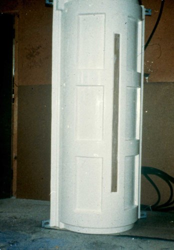
Figure 1 - Close-fitted dielectrically shielded anode
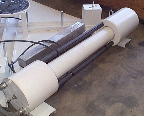
Figure 2 - Buoyant anode module - MMO anode rods arranged to minimize end effect
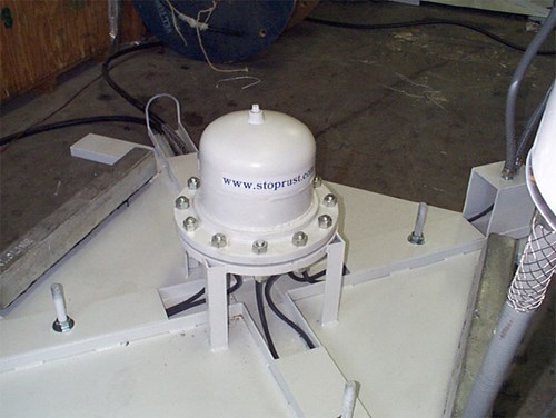
Figure 3 - Pressure compensated oil-filled junction box on a retrofit sled
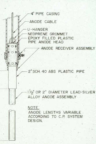
Figure 4 - Typical suspended anode
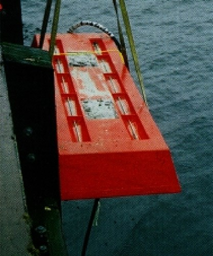
Figure 5 - Typical gravity sled
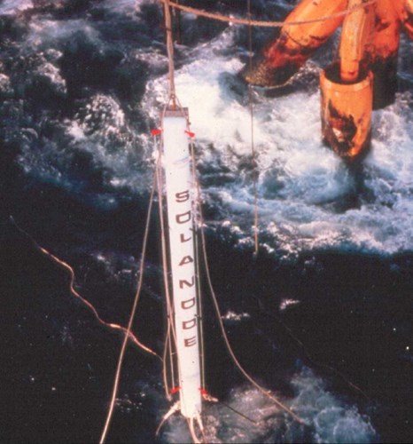
Figure 6 - Single-buoy anode
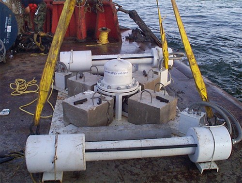
Figure 7 - Multi-buoy anode sled ready for offshore deployment
References
1. Bjorn Linder - "Magnetite Anodes for Impressed Current Cathodic Protection" Materials Performance, August 1979.
2. M.A. Warne - "Precious Metal Anodes - Options for Cathodic Protection" Materials Performance, August 1979
3. Richard A. Lowe -" Platinized Titanium as Anode Material" Materials Performance, April 1966
4. MA. Warne, P.C.S Hayfield- "Platinized Titanium Anodes for Use in Cathodic Protection"Materials Performance, March 1976
5. P.C.s Hayfield- "Electrochemical Properties of Niobium in Impressed Current Cathodic Protection" Materials Performance, November 1981
6. Robert Baboian - "Performance of Platinum Clad Columbium Impressed Current Anodes in Fresh Water" Materials Performance, December 1983
7. K. D. Efird- "Current Waveform Initiated Corrosion Failure of Platinum Niobium Anodes in Seawater Cathodic Protection Systems" Materials Performance, June 1982
8. Tim French-Mullen - "An Impressed Current System for the Protection of Offshore Platforms"
9. Materials Performance, November 1980
10. J. D. Edwards et al- "Retrofitting Offshore Structures with Tubular Metal Oxide Activated Titanium Anodes" NACE - CORROSION 91 ,Paper 91240.
II. M. L. Smith, C. P. Weldon - "Impressed Current Tensioned Anode Strings for Offshore Structures" NACE - CORROSION 97, Paper 97476
Want to receive an email when Deepwater publishes new corrosion-related technical papers, case studies, and more? Sign up for our Corrosion Newsletter using the form below. You can unsubscribe at any time.
Related Content
Spotlight

Related products & experience


Technical papers


