Technical Paper
Monitoring CP performance in deep water production systems
by Jim Britton (1990) from Materials Performance Magazine
This paper was originally written for the Corrosion 89 conference put on by NACE. It was subsequently published in Materials Performance in 1990. In 2005, Mr. Britton wrote an update to address the changes in corrosion control technology for deep water production equipment that had taken place in the interim. The original paper is presented here for educational purposes.
Part Two: Monitoring CP System Performance in Deep Water Production Systems (2005)
Abstract
Increasing interest in deep water offshore areas has presented a whole set of new unsolved problems to the corrosion industry. Several programs are in progress which are attempting to formulate revised cathodic protection design criteria for the deep ocean. The lack of historical data, combined with the increased criticality of accurate corrosion control design in these areas, serve to accentuate the need to be able to monitor the performance of the cathodic protection system once installed. The structural designs being considered for deep water production also present new problems which cannot always be addressed with standard monitoring methods and technologies. This paper will identify some of these problems and offer some generic solutions which should serve to increase the overall reliability of future deep water corrosion control systems.
Introduction
When considering deep water facilities, the monitoring of cathodic protection systems serves two basic functions. Firstly, the correct operation of the system is verified, and secondly, invaluable data is gathered which can be used to guide future designs. For this reason it is desirable for a monitoring program to satisfy both operational and research requirements without significant cost penalty. As more experience in various areas and at various depths is garnered, it will be possible to revert to purely operational monitoring.
Early considerations
In the formulation of a monitoring program, it is important to start planning at an early stage in the project. If the design is reviewed by a corrosion engineer, many potential hot spots can be designed around or eliminated from the final design, or at least their criticality can be well appreciated and detailed attention given to both the corrosion control system and the monitoring of the area. Another major consideration, often overlooked, is the need to ensure the quality of the materials used in the corrosion control system. This has been handled better on the coatings side but has been less stringent when considering the anode materials. Naturally the performance of the anodes from an electrochemical standpoint is critical, if they fall short, it could result in the need to undertake an extremely costly system retrofit. Third party verification of testing methods and results can help prevent this occurrence.
Splash down systems
When considering a steel structure in sea water with a galvanic cathodic protection system, the most critical period during the polarization process is the first 6 - 12 months. If the structure achieves full polarization during this period, and maintenance current density levels are as projected, then it is unlikely that any long term problems will develop. This phase can be monitored with a fixed system wired into a data logger. The logger can be located either subsea, for later recovery or downloading from a ROV, or, in the case of a jacket, the unit can be located on the (+)10'0" level of the platform during launch.
ROV intervention
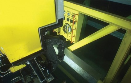
Most deep water production facilities will have a dedicated ROV to support ongoing drilling and production operations. It makes economic sense to utilize this facility when formulating a monitoring program. A range of ROV interfaced systems are available for pipeline and structural surveys. Optionally intelligent fixed monitoring systems can be deployed which will store data, this data can be periodically transmitted to the surface via the ROV umbilical cable.
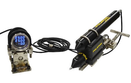
Several portable measurement systems are available for ROV interface. It is important when employing such systems to ensure that signals are not corrupted in the ROV umbilical cable, which is used to transmit data to the surface. The most reliable method to eliminate this problem is to digitize the data on the ROV before it goes into the umbilical cable, this has the added advantage that the data can be handled with a computer topside. Such systems are in wide use in the offshore area (2).
When considering an ROV mounted system it is a good idea to provide a subsea ground facility, usually in the form of a tip or spike contact, this serves several functions. It can be used to compare a subsea ground with a topside ground, hence if any signal corruption exists in the ROV umbilical it can be immediately corrected. It is used to provide a reference ground on systems such as subsea completions where there is no topside structure. It can be used to verify electrical continuity or isolation of subsea structures such as riser clamps, retrofitted anodes, piles within pile guides, etc. Finally, one system uses the tip as one of two electrodes in an on-line resistivity measurement system.
Where to monitor
The specific locations selected for monitoring will obviously vary with the design of the structure in question. There are however some typical guidelines which should be followed. When considering operational monitoring, as opposed to research testing, it is important to assess the critical areas on the structure. This criticality should be weighed both in terms of risk and consequences of under-protection or failure as well as the difficulty of affording adequate protection. Load bearing nodes are prime candidates since they are both structurally critical items, as well as being more difficult areas to protect. Heavily congested areas, such as conductor bundles, tUbing runs and skirt pile areas, are also difficult to polarize, and should be considered for monitoring. Other critical locations are risers, pilings near the mud line, subsea well heads and mooring or tethering systems. Most offshore structures, whatever their design, are symmetrical about two axes, the design of the cathodic protection system will normally follow this symmetry. It is therefore feasible and rational to select typical quadrants for monitoring thus covering all critical areas with the minimum of instrumentation.
Reference electrodes
There are two basic electrode types used in sea water cathodic protection monitoring, silver/silver chloride and zinc. It is not uncommon to use twin element electrodes using both types in the same housing. This gives an on-line calibration facility as well as a degree of redundancy should one of the electrodes fail. In the experience of the writer, the zinc electrodes, while slightly less accurate, are far more reliable for long term service in sea water.
Bleed current - In order that zinc electrodes do not form a passive surface oxide layer, it is necessary to allow a small current discharge to drain from the zinc electrode. This has been achieved historically by grounding the electrode to the cathode through a relatively high value resistor. A more reliable method is to provide a small area of steel, still isolated from the main cathode, at the the zinc electrode. This can be achieved by casting the electrode onto a steel core and leaving a small surface area of the core exposed to the electrolyte. The relative surface area of steel to zinc should not exceed 1:2. This method ensures a constant bleed current which does not flow in the measurement circuit, and results in a generally more stable signal.
Current density monitoring
We know from experience that the initial current density provided to a sea water immersed cathode is the major factor determining the polarization behavior of the cathode. This effects the long term current density requirement to maintain the polarized condition. For these reasons it is desirable to monitor current density on the cathode. A number of options are available.
Insulated sections - Goolsby (I), described the use of insulated sections on the monitoring of the Ellen Platform on the West Coast. A section of the structure is overlaid with a known surface area of steel which is insulated by a heavy neoprene coating from the base 'structure, the former being grounded to the structure with a heavy gauge cable via a calibrated low resistance shunt. Current picked up on the test section can then be measured and the current deduced. This is a reliable method of monitoring current density although somewhat costly to install.
Current density sensors - The current density sensor is a modification of the wrap section. The major differences being that the sample cathode is attached directly to the structure via a steel rod, a very sensitive current measuring device is deployed around the rod and the current density measured directly. The advantage of this system is it's small size, which allows monitoring in more confined areas. The major disadvantage is the fact that an excitation voltage is required to power the current sensing toroid and the inherent unreliability of this type of device in this service.
Anode monitoring - Another approach to current density monitoring is to measure the output of a good sample of the anodes in the system, the average current density can then be approximated with simple calculation. This method is somewhat less reliable since many assumptions have to be made.
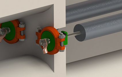
It is useful, however, to consider monitoring representative anodes. Goolsby (1) described a large diameter current sensing toroid which could be placed around the standoff pipes connecting the anode to the structure. This is an accurate method of current measurement but is subject to the same unreliability factors as the current density sensors which work on a similar principle. A more reliable, although less accurate method, is to insulate the anode from the structure using either insulated flanges or isolation joints, and to provide a calibrated by-pass through which the current can be determined.
Field gradient measurement - All of the above methods are based on fixed instrumentation installed on the subsea structure. The only method presently known to give the flexibility of portable measurement on existing structures is the electric field gradient measurement (EFG). This involves the use of a pair of closely matched reference electrodes, (usually saturated silver/silver chloride) arrayed at a known spacing and presented to the structure such that the pair of electrodes are normal to the axis of the structural member under investigation. If the diameter of the member, the sea water resistivity, the electrode spacing relative to the member are all known then the measured field gradient voltage can be converted to an approximate surface current density value. Such a system is described by Britton & Holt (2). This method does have certain limitations however. It is not valid in complex geometry situations, around nodal areas for example, since the large number of intersecting fields causes error in the actual value measured. This same method can be applied to anodes to approximate their current output.
Frequency of monitoring
As previously stated, once a galvanic CP system has achieved optimum polarization, and, assuming that the quality of the corrosion control system materials has been verified, there should be no significant time based variation in system performance over the design life. This would suggest that infrequent monitoring will suffice. There are, however, other factors involved. Any structural modification, such as the addition of new well, the addition of new pipelines etc., can upset the systems equilibrium, this is, however, unlikely in normal operations. The regulating authorities and insurers also have to be considered, as does the need to perform periodic structural integrity surveys, these factors will normally result in either annual, three yearly or five yearly ROV surveys of the structure, depending on geographic location. If an ROY is deployed to conduct a visual survey, it makes sense to interface a corrosion measurement system which can also provide at least a cathodic protection potential survey. If a fixed on-line system is provided, the need for detailed subsea surveys can be greatly reduced.
Acoustic systems
The use of acoustically linked monitoring systems has some track record in the North Sea. There are, however, a host of limitations which will almost certainly render such systems unfeasible for operational monitoring. The main disadvantages being cost and reliability.
Hard-wired systems
The use of hard wired monitoring systems presents the most attractive option for many types of structure. The technology has been widely used, again, mainly in the North Sea, with a reasonably high success ratio. There are, however, some drawbacks. In harsh environments, it is desirable to protect cables passing through the splash zone, this involves the installation of conduits for this purpose, such installations can become prohibitively expensive if not included on the initial design of the structure. Hard wired systems may not be practical for other types of structure such as floating production systems or tension leg platforms.
Intelligent subsea systems
These systems will find greater application in the new generation of offshore structures for deep water. The sensors will be hard wired into a subsea data gathering and processing unit. The data being accessed by an ROY equipped with a data transfer probe, the same probe will be used to recharge batteries in the system. This technology is still in the developmental stage but initial results are promising. Such systems will no doubt find application in the monitoring of other subsea conditions such as pressures, flow rates, temperatures, etc.
Capillary systems
The use of dielectric capillary arrays to monitor inaccessible areas has been a recent innovation, for the use of a sea water filled capillary designed for ROV intervention, eliminates the need for permanently mounted reference electrodes and allows hard to reach areas to be monitored. The reference electrode with a male sealing cone is attached to the ROV manipulator, the end of the capillary is fitted with a female conical stabbing guide located for easy ROY access.
Such a system provides the only realistic solution for monitoring certain areas on deep water designs, the system is relatively inexpensive to install and once in place, has a design life equivalent to that of the structure itself.
Summary
The wide range of options available to the oil and gas industry for the monitoring of cathodic protection can cause a degree of confusion. It is important to stress the fact that no single "off the shelf" system is suitable for all cases. The monitoring program should be formulated to suit the particular circumstance. Whatever the final solution, the most successful programs will be those which start at the project design stage rather than those that are included as an afterthought.
There is no question that the level of monitoring, at least in the early stages of a project, has to increase as structures go deeper and become more complex. Only then can the corrosion industry respond with accurate reliable cathodic protection designs that work first time.
References
1. A.D. Goolsby, :'The Results of Monitoring Platform. Ellen Cathodic Protection for Two Years", CORROSION/83, Paper No. 217, National Association of Corrosion Engineers, Houston, Texas, 1983.
2. J. N. Britton, R. J. Holt, "A Computerized Cathodic Protection Survey System for Offshore Platforms", Materials Performance, Vol. 25, No.4, p. 46, 1986.
Related Content
Monitoring CP Performance in Deep Water Production Systems
by Jim Britton (1990) from Materials Performance Magazine
This paper was originally written for the Corrosion 89 conference, put on by NACE. It was subsequently published in Materials Performance in 1990. In 2005, Mr. Britton wrote an update to address the changes in corrosion control technology for deep water production equipment that had taken place in the interim. The original paper is presented here for educational purposes.
Part Two: Monitoring CP System Performance in Deep Water Production Systems (2005)
ABSTRACT
Increasing interest in deep water offshore areas has presented a whole set of new unsolved problems to the corrosion industry. Several programs are in progress which are attempting to formulate revised cathodic protection design criteria for the deep ocean. The lack of historical data, combined with the increased criticality of accurate corrosion control design in these areas, serve to accentuate the need to be able to monitor the performance of the cathodic protection system once installed. The structural designs being considered for deep water production also present new problems which cannot always be addressed with standard monitoring methods and technologies. This paper will identify some of these problems and offer some generic solutions which should serve to increase the overall reliability of future deep water corrosion control systems.
Want to receive an email when Deepwater publishes new corrosion-related technical papers, case studies, and more? Sign up for our Corrosion Newsletter using the form below. You can unsubscribe at any time.
