Offshore cathodic protection system management: A 21st century approach
by James N. Britton (2004)
 Download this paper
 Abstract
This paper describes several common modes of early coating failure that lead to corrosion problems on offshore platforms. Symptoms are analyzed, and solutions are presented. The work is based on the examination of two offshore platforms in the Gulf of Mexico that had been in service for less than 18 months.
Introduction
Many offshore structures, platforms and pipelines, will require a cathodic protection retrofit in the next several years. The required life extension will vary from one or two years through adding over 20 years to the original design life of the equipment. The historical approach to retrofit has been to replace anodes on a one for one basis, but this approach is very costly and unnecessarily dangerous. There is a tendency for the industry to misinterpret the reasons why cathodic protection systems for new structures are designed the way they are: they are invariably designed to satisfy installation requirements.
For example, a pipeline bracelet anode is designed to look the way it does to facilitate pre-installation of the cathodic protection system on the pipeline. The shape of the anode allows for the pipe to be easily laid with the anodes already in place. In truth, from the CP engineer's standpoint (trying to maximize efficient use of the sacrificial alloy), the design of the bracelet anode is possibly the worst that it could be. The resistance is high, the utilization factor is low, the manufacturing cost is high and the "throwing power" is poor. But bracelet anode shapes do not inhibit the installation procedure, and in that way, the bracelet is quite suited.
Another example is the conventional platform anode; they are attached by welding extremely stout pipe cores to the structure. Why? .. To withstand launch forces and/or pile driving during installation. Again, the cathodic protection design is predicated on the installation method that will be used. Is this the best way to install an anode on a large bare steel structure, to maximize the amount of cathodic protection delivered per anode? .. Of course not; utilization is reduced, the standoff distance is not optimized and the cost of all those welds is very significant. When one is charged with designing a retrofit cathodic protection system, as the structure is already in place most of these original constraints are not relevant. Thus, one should not be constrained in any way by the original design methodology when designing the retrofit.
Cost of retrofit
When analyzing the cost of a retrofit project, the driver is always the same. Cost of installation always drives the project budget. Therefore, the design should focus on reduction of installation cost without sacrificing mechanical reliability. Some of the obvious ways in which this may be accomplished are:
On pipelines:
1. Minimize the number of locations on the pipeline that have to be visited.
2. Select areas for anode attachment where the depth of cover is minimal or the pipeline is exposed on the seabed.
3. Minimize bottom time requirement at each location.
4. On deeper projects, use ROV's rather than saturation divers.
5. Carefully evaluate and compare costs of 4-point moored systems vs. dynamically positioned equipment.
6. Evaluate impressed current, sacrificial anode and hybrid solutions during the design phase.
7. Have the flexibility to adjust the retrofit plan offshore based on survey results obtained as the installation progresses.
On platforms
1. Minimize the number of anode installations.
2. Minimize the amount of marine growth removal.
3. On deeper projects, use ROV's rather than saturation divers. Use shallow diving support to accomplish high dexterity tasks such as marine growth removal, installation of splash-zone pull tubes etc.
4. Have the flexibility to adjust the retrofit plan offshore based on survey results obtained as the installation progresses.
5. Carefully plan topside rigging and set equipment prior to mobilization of the subsea installation spread.
6. Evaluate impressed current, sacrificial anode and hybrid solutions during the design phase.
Retrofit design
Just as cathodic protection designs for new construction are made to facilitate installation of the asset, the cathodic protection design criteria for retrofit projects are designed to essentially to polarize a structure from native state potential and to provide adequate redundancy in design to allow for some system damage during installation (or for unknown environmental affects). As installation cost of the CP system itself is negligible for new construction, there is little incentive to "over-optimize" the design, if it entails any added risk. However, when considering a retrofit there are a number of major differences that should be reflected in the design criteria selection:
1. In all cases there will be some degree of polarization remaining from the original CP system, even if the structure has fallen below "protective potential criteria." In many cases the structure will still be adequately protected but will have heavily depleted anodes (i.e. not protected for long).
2. Asset life extension requirements may only be a few years, in which case it may not be necessary to optimize protective potential levels in the design.
3. We have the benefit of being able to perform a survey, to accurately define the condition of the cathodic protection system, and to measure the existing polarization characteristics (current density vs. potential).
4. We have the advantage of being able to monitor both anode and cathode response during the retrofit to verify design predictions.
As a result of these differences, it is rarely (if ever) required when designing a CP retrofit to provide the same current density as one would for a new structure. And if existing maintenance current density can be demonstrated to be much lower than conventional wisdom would dictate is prudent, significant savings can still be realized [1].
The importance of survey
The value of a well conceived and executed survey cannot be over estimated. This is true of both platforms and pipelines but particularly so with buried or partially buried pipelines. Concerning pipeline survey: high resolution type surveys [2] are highly recommended, while remote or semi-remote (trailing wire or tow fish) type surveys provide little or no useful information. The most important data obtained from a detailed pipeline survey, in order of value, are:
1. Line location - To efficiently install a retrofit cathodic protection system, having an accurate position on the pipeline is essential (though not by any means given), particularly if the line is buried. The hourly rate for the offshore equipment necessary to effect a pipeline retrofit makes it quite unacceptable to waste any time trying to locate the pipeline during the installation process itself.
2. Line depth of cover - Knowing where the pipeline is exposed or has only minimal cover will save significant amounts of time attaching the retrofit anodes to the pipe. If a retrofit site where the pipeline is buried 2 m deep is selected during the design, it could take divers many hours to excavate the pipeline before being able to attach the new anodes. Once excavated, they would be further hindered working in a deep hole, where visibility and maneuverability could be extremely limited.
3. Knowing cathodic protection system performance - By measuring the field gradients as well as potential, the resilience of the cathodic protection system can be estimated. CP designers can also take into account areas of significant coating damage. If an ROV can fly the line, there is always the chance of obtaining a visual inspection of one or more anodes. Combined with accurate potential data, actually seeing the state of the current anodes can provide invaluable information to the CP designer.
4. Verification of environmental conditions - The survey will give a good indication of seabed conditions, current velocities etc., as well as giving accurate sea-water and more importantly, mud resistivity information.
Armed with this survey information, the cathodic protection designer can first select ideal sites for retrofit anode locations, based on the depth of cover survey. Knowing the current density requirement and general coating condition facilitates accurate application of attenuation modeling to optimize spacing between retrofit sites. Knowledge of the mud resistivity allows accurate calculation of current outputs from various anode arrays.
On platforms it is the same story. Using an intelligent survey approach [3], [4], will yield valuable information on a cathodic protection system's performance. Again, structure potential data alone do not tell the whole story. Estimating anode depletion percentage is another area where mistakes are often made. Figure 1 shows a dimension vs. volumetric relationship on a typical platform anode. As can be seen, the first 12 mm of cross sectional reduction equates to 12.6% loss of metal. Near the end of an anode's life the same reduction represents only 7.1% volumetric loss. Thus it is important to take accurate measurements on a few cleaned (water blasted) anodes to get an accurate status on remaining anode material. The benefits of an intelligent platform inspection are, in order of value:
1. Polarization data - Knowing the existing maintenance current density on a structure gives the CP designer a precise benchmark from which to work. This will always result in a lower (but still safe) current density target for the retrofit anode design. This saves time and money without adding risk.
2. Anode performance - Knowing the current output range of the existing anodes and their average degree of consumption will allow a more precise prediction of the remaining life of the system. With this information, an operator could responsibly defer a retrofit for one or more seasons, again with no risk.
3. General platform condition - A typical survey will also include an evaluation of the seabed conditions, as well as information about silt / scour and seabed debris. These are invaluable data if a seabed pod or sled approach is considered, or if access to mud-line framing is required. Extent and thickness of marine growth will affect structural attachments. Verification of the type and location of the original anodes may prove useful if they still output significantly enough to be used to support new retrofit anodes. Ascertaining existing corrosion damage is also incredibly important, as some heavily corroded structures may not be candidates for certain kinds of retrofit.
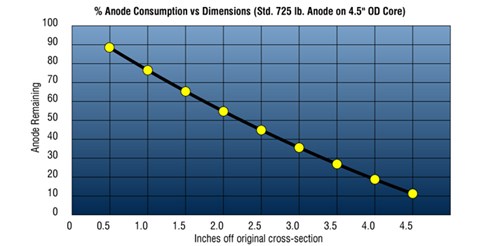
Figure 1 - Anode consumption vs. cross section loss
Case histories
To illustrate more specifically some of the points mentioned in the above paragraphs, three case histories will be discussed. These projects were completed in the Gulf of Mexico in 2000, and while not all of the procedures follow the ideals outlined, the application of the basic principles is apparent, as are the documented performance data and cost savings.
Case history No. 1 - 12" Oil pipeline
The asset - This pipeline was installed in 1973 and runs from an offshore platform in 76 m (250 feet) of water to an onshore terminal 90 km (56 miles) distant. From the platform to about kilometer 24 (mile 15) the line is bottom laid, although the location of the line near the Mississippi River delta has resulted in much of the pipeline silting over. The next 32 km (20 miles) of pipe was laid in water that was less than 125 m (200 feet) deep and was buried to a depth of 1.5 m (5 feet). The final 34 km (21 miles) are laid through wetland (swamp) in a pipe canal and buried a minimum of 2 m (6 feet). The offshore section (56 km / 35 miles) of the line was originally protected with zinc anode bracelets; the wetland section was originally protected with a combination of impressed current CP and zinc bracelets. Precise records of where the bracelets started were not available. The pipeline has a 25mm (1") thick concrete weight coat.
Survey - In 1997 the offshore section of the pipeline was surveyed using a three electrode system [2]. The survey results showed that the pipeline was still at protected potentials but that the anode bracelets were heavily depleted. The survey also showed the depth of cover on the pipeline ranged from exposed to > 3 m (10 feet). An accurate as-built plot was generated, which showed the actual position of the pipeline to be as much as 30 m (100 feet) off from the original "as built" survey.
Anode retrofit - In 2000 the pipeline owner decided to retrofit cathodic protection for the offshore section of the pipeline (56 km / 35 miles). The desired life extension for the asset was 10 years. Review of the riser potential showed a very small decline in protected potential from the survey conducted 3 years before.
The retrofit design utilized pairs of sleds located either side of the pipeline as shown in Figure 2. Attenuation models were used to set the maximum spacing between anode sled installations; this resulted in a value of 3650 m (12,000 feet). Points were selected where the depth of cover was minimal or the pipe was exposed, and a total of 28 sleds were proposed for 14 sites along the pipeline. It was apparent that the majority of time on bottom would be taken up exposing the line and removing concrete (to obtain sufficient electrical connection with the pipe). The asset owner decided to use a continuity clamp (RetroClamp) designed by Deepwater Corrosion, that could be installed without having to expose 360 degrees of the pipeline or having to remove a large area of concrete weight coating.
The clamp system used Figure 3. allowed for only a small circle of concrete (100 mm / 4 inches in diameter) to be removed on the top of the pipeline, and required only 180 degrees of the pipeline to be exposed. It was also necessary that the clamp would pull off the line if snagged and that continuity could be assured over a wide range of temperatures without inducing a stress raising point on the pipeline. The clamp shown is a constant tension device with a hollow ground soft contact-tip that will indeed separate from the pipe if snagged, without damaging the pipeline itself.
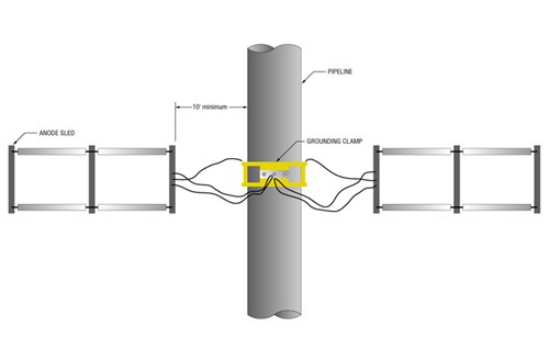
Figure 2 - Typical pipeline anode sled arrangement
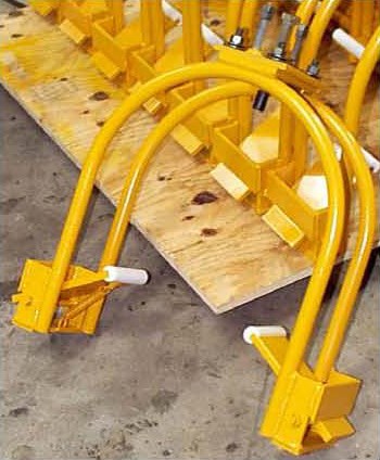
Figure 3 - Retrofit clamp for pipelines
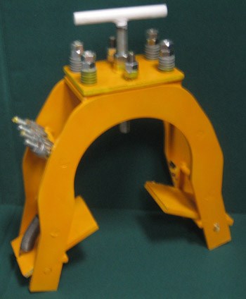
Figure 4 - Constant tension retrofit clamp for weight-coated pipelines
Want to receive an email when Deepwater publishes new corrosion-related technical papers, case studies, and more? Sign up for our Corrosion Newsletter using the form below. You can unsubscribe at any time.
Related Content
Spotlight

Garden Banks 191-A Anode retrofit
Project case study: ICCP anode sleds retrofit on a GOM fixed platform
Read moreRelated products & experience


Technical papers


